The Blender Conference 2022 was an opportunity for part of the Geometry Nodes team to get together. To make the best out of having the entire core team in the same place, a 4-day workshop was held in Amsterdam.
Present there were Dalai Felinto, Hans Goudey, Jacques Lucke and Simon Thommes, besides occasional visitors such as Brecht Van Lommel, Jeroen Bakker and Julien Kaspar.
Development Process, Recap
For an overview of the Geometry Nodes development process check the Blender Conference 2022 video:
After tackling procedural modeling and initial hair grooming, the next big target for Geometry Nodes is simulation. This is not trivial, and one of its show-stoppers was that a more clear design was required.
This wasn’t the only long-standing topics that could use an all-hands on board meeting though. While a lot can be done with online collaboration tools, a big white board and being in the same room goes a long way. The workshop started by collecting a few of those topics. The main ones are presented here in-depth, but you can skip to the end of this article to find the complete list.
Those topics are:
Simulation
Geometry Nodes has focused on animation so far. In those cases each frame can be calculated independently of any other, and no “state” carries over. Simulation on the other hand is about using the result of one frame to influence the next one. That way even a set of simple rules can lead to complex results, with the passing of time. The most common type of them is physics simulation, with specific solvers for physical phenomena.
Local vs Global
Some simulations are local, (e.g., a waving flag), while others are global with multiple objects interacting with each other (e.g., a soccer ball against a goal net). In Blender at the moment cloth and hair simulations are local, with no collision calculated between simulated objects, while rigid-body is global.
The idea is to first support local simulation, and later to extend the design to account for global simulation.
Simulation Nodes
People do so much with the currently available tools that just giving access to the previous frame’s data would make so much possible. Following this premise, a simulation is made of two dedicated nodes, and can use all the other nodes already available in Geometry Nodes.
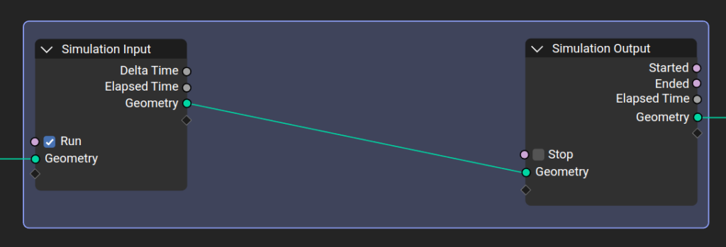
For the input, artists can control when the simulation should start to run, and pass geometry and values to be simulated as fields. The delta time (difference of time since the last simulation step) and the elapsed time are available for the simulation. The regular nodes can be used inside the simulation region.
The simulation output node allows the simulation to stop based on an internal status, as well as receive the geometry and fields that are passed to the next step of the simulation. Outside the simulation region it is possible to know if the simulation started/ended, the elapsed time, and to get the simulated geometry with its simulated attributes.
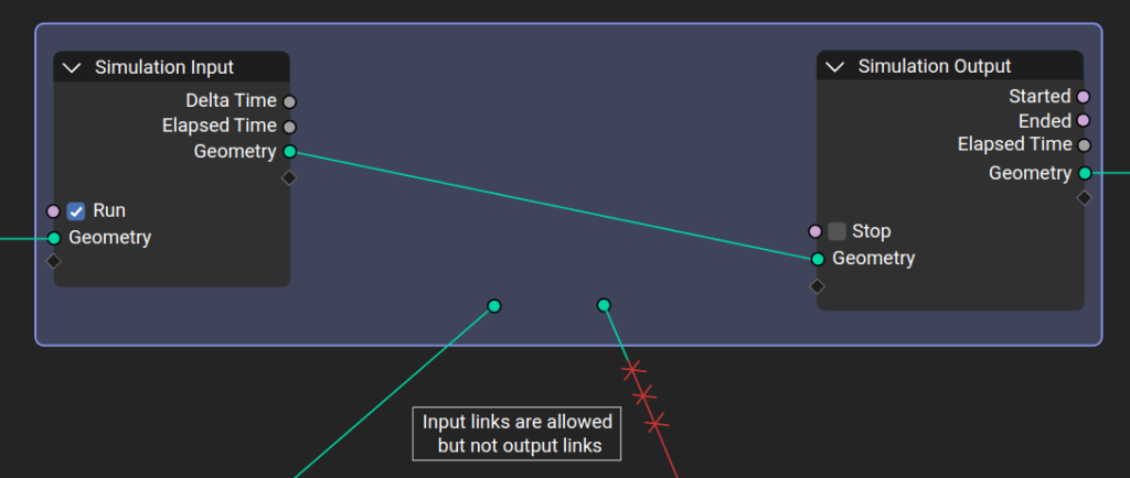
The inputs that are connected to the Simulation Input node are evaluated only once, at the beginning of the simulation, passed to the next simulation state and eventually outputted. Other nodes can be linked inside the simulation region from the outside. Those are re-evaluated every step based on their value at the given frame.
By design, it is not possible to have any link going towards outside. The result of the simulation can only be accessed via the Simulation Output node. This also allows sub-frame interpolation for motion blur.
Simulation Clock
At first the simulation will be tied to the animation system, besides support for sub-steps. It will only be evaluated while the animation frame changes, and it can be cached like the existing physics simulations in Blender.
Eventually simulations will be able to run on their own clock. That physics/real-time clock should run independently from the animation clock, allowing users to setup and control the simulation interactively.
Loops
Back in May 2021, “generator artist” Erindale Woodford was asked to provide a comprehensive feedback on how would they achieve arced walls, and which showstoppers may get on the way.
Although the walls and arcs were doable, growing Ivys were too much work until there were a way to iteratively loop over geometry components.
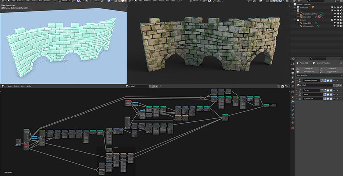
There are two main loops that were expected in a node-tree, and both can be built on top of the simulation design: Serial loops and Parallel loops.
Serial Loop
Sometimes a set of node logic needs to be repeated a few times in a row, in a Serial loop. Following the design of the simulation system, users can control the loop parameters (e.g., max iteration) and decide when to stop.

There are some similarities between the serial and the simulation loop. However, while the simulation loop is tied to time progression, the serial loop is fully evaluated every single frame.
Parallel Loop
If instead of running things sequentially they run simultaneously, we have a Parallel loop. There are two modes planned: Count and Elements.
Count is a more generic loop that can output a geometry (or in the future, lists) that is a combination of the individual geometry bits created in parallel. The output is joined similarly to the Join node, and individual values are outputted as fields of the combined geometry.

The Elements mode is specifically to iterate over the elements of a domain in the geometry (points, edges, …). This mode outputs the part of the geometry that corresponds to the current iteration.
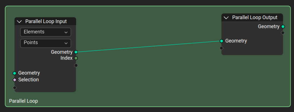
Nested Loops
Loops can be inside other loops, inside simulations and on and on. To see how nested loops may look like, here is a node-tree that can connect points to each other based on a distance parameter.

Visuals Explorations
While the designs presented here are close to “pixel perfect”, their main focus is on the functional level. There is a lot of room to explore on how those features will end up looking, and this was left as a follow up after the workshop.
There are a few early explorations that are worth sharing though:
Convex Hull

Overlaid Input and Output
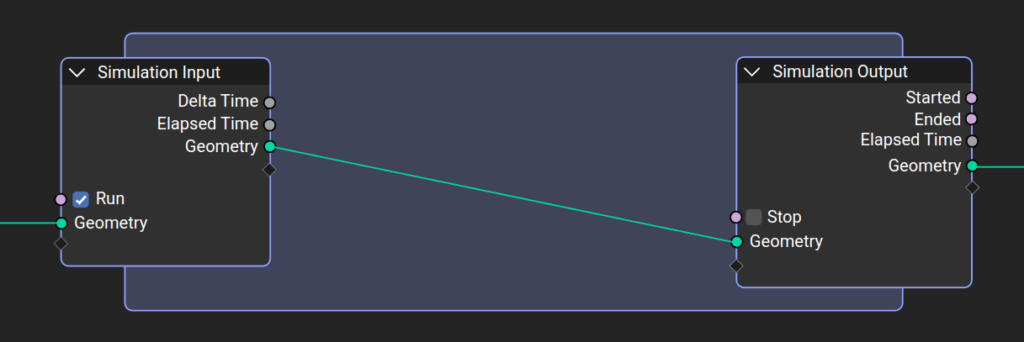
Other ideas that were discussed:
- Aligning inputs and outputs on the same row
- Node panels
Geometry Object
Geometry Nodes allow an object to have geometries of different types. The same object can have volume, curve, point cloud, mesh and instance data. This is at odds with the original design of Blender, where an object type is rigid and would determine the available edit modes as well as the panels in the properties editor.
To make matters more complicated, since the new hair system it became more evident that would be good to have a way to freeze parts of a node tree and edit the (baked) generated geometry. That leads to any object potentially having multiple editable meshes, or a combination of meshes, curves, and other geometries.
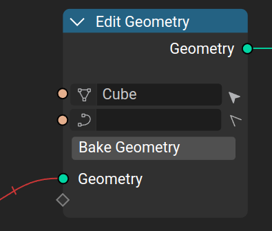
A solution for this is to unify all the geometry-related object types into a Geometry type. Those objects should support multiple editable geometries, while the active edit data determines which modes and panels are available.
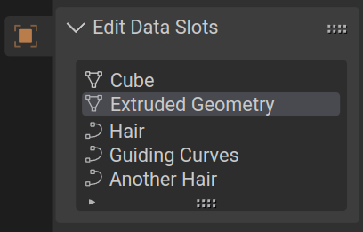
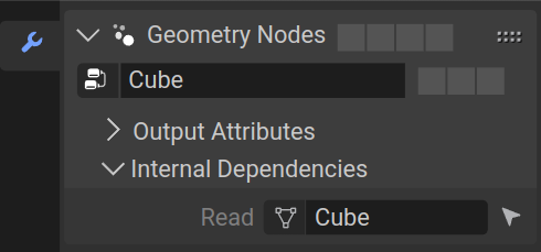
The primitives in Blender (cube, cylinder, …) can have an initial modifier with a geometry nodes setup with the Edit Geometry node. For users that don’t want to dive into the nodes and want to go straight to edit mode there would be no functional difference.
Menu Switch
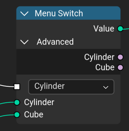
One of the guiding principles of Geometry Nodes is that any built-in node could be re-created by a user with a node-group. So far the biggest limitation for this were the drop-down menus some nodes have as part of their options.
The Menu Switch, together with Menu sockets should allow users to close that gap. Editing the menu entries names is done in the Node properties in the properties region.
Other Topics
The list of topics covered in those few days is extensive:
- Spreadsheet Editing
- Import Nodes
- Attribute Editing
- Dynamic Socket Type
- Dynamic Socket Count
- Automatic Caching
- Freeze Caching
- Geometry Object
- Usability
- Node UI
- Math Nodes
- Preview Node
- Comments
You can read more about those topics in the complete report.
Support the Future of Blender
Donate and support Blender Foundation to work on core Blender development.
How do i get started? I have zero experience with geometry nodes. Are there any beginner tutorial you can reference?
There are plenty of tutorials on the internet, including a training by Simon Thommes as part of the Blender Studio.
Maybe you can treat a loop just like a node group with predefined outputs and inputs. Similarly to node groups, you can tab into the loop to edit it. This should keeps the relevant nodes nicely contained within the loop, though it’s an extra step to get in the loop and start editing.
Hi Antoni,
We considered that. However it adds a lot of burden to pass nodes in and out of the “simulation group”.
This would also force us to split the group inputs in two groups:
* Preserved state – the current “inputs” we have (evaluated only at the begin of the simulation, and further fed into the next iteration).
* Other inputs – evaluated every frame/state.
Right now we treat the other inputs as regular links in the node-tree, since they behave the same for simulation and for the rest of the tree (evaluated every time). And keep the special inputs only for the Simulation nodes.
It may make the distinction between both a bit less clear, but it makes it easier/faster to connect random parts of the tree into the simulation.
I think about it.
And I think why it was decided to make separate simulation nodes instead more fundamental ablility to store any attribute or geometry.
For example I want to store X each 5 frames, and next 4 frames i do not need to change this field for 10 million of points. Why should I do it each frame?
Or should I off my sim during 4 frames?
At least I hope, there will be «buffer attribute» function as alternative.
Or should i just switch sim and switch routes?
——————————————————————————————————————
About math node separation.
I hope, there will benot too much. For example only math, trigonometry and compare nodes
> Or should I off my sim during 4 frames?
You just turn your simulation off during 4 frames (e.g., with switch nodes).
Will a decimate (or unsubdivide) node for geometry nodes in the future? I mean, I am all for simulation nodes, but what about a decimate node?
Hi, this is unrelated to this blog-post. To keep an eye on the overall roadmap of geometry nodes it is better to check the meetings and community tasks in the workboard.
You can follow and help testing the decimate node progress here: https://developer.blender.org/T89051
Really exciting developement. I’ve been waiting for this ever since seeing the crazy things people could do with the object buffer hack.
As for the design, any reason you guys with the convex hull instead of a regular frame? The overlaid input and output option looks much more elegant and clean imho. We have rectangular nodes on a square grid, the convex hull looks a bit out of place. Plus, people already use frames to organize their nodes soI think something simlar is more fitting.
We are still exploring the idea of frame vs convex hull. But the main appeal of the convex hull is that it keep most of the other nodes outside of it (unlike the frame). And for the current design nodes will naturally be connected from outside the simulation region into the simulation nodes directly. Forcing a square framing on them means they would end up inside the frame too often even though technically they don’ t have to be,
Would be worth checking out this RCS proposal for lists to implement with loops since the two could work well together: https://blender.community/c/rightclickselect/1Wxm/
Please excuse me, I did not fully understand the idea of developing the implementation of a new node system for simulation. Will simulation nodes be provided as an additional feature with functions and thus more flexible control, or will it be a complete replacement for the physics tab in the properties editor?
Thank you in advance if you take a little time to my question
It may be too early to say in definitive, but the plan is to integrate the new physics system with geometry nodes. We can still have per-object physics specific options set on the object level, outside the geometry nodes.
That said, the simulation system is generic and fully nodal. As you said it, a system with more flexible control where the “solver” is created by the users using the existing generic nodes. It won’t replace physic based simulation solvers, but co-exist with them.
Thank you for the detailed answer of the Dalai! I am delighted with what you are doing and with your ideas, I wish you good luck in your plans!
It’s great how looping and simulation is not dependant on grouping. Keeping things on the same level if you want to is a very welcome change for me
So Manuel from Entagma is collaborating with you guys? <3
I did talk to Manuel before, and I’m very happy to see them covering Blender/Geometry Nodes in their channel. But in this case it was basically just me going after the tutorial they published and trying to see how that could be replicated with loops.
I think it would be best if you guys would work with the Entagma guys, especially with Manuel, considering the depth of his knowledge about CG, math and proceduralism and decades of industry experience working with various DDC and facing numerous challenges, I think they’d have a much better idea about the strengths and weaknesses of other DDCs and where Blender can shine and also excel. Not to mention now he is a university professor teaching people CGI. Simulation is one of the things that has kinda lacked in Blender for a while and wasn’t really the strong point of Blender, currently only one software rules everyone else in this department, not to mention it’s not an easy task to make great simulation framework that’s powerful, extensive and also user friendly to use either, good luck guys.
Anyone willing to contribute to the project is welcome to the module meetings. There is information about them in the development channels/pages.
As for Entagma specifically they follow Blender development (see their latest video on the simulation hack using buffer). And the geometry nodes team follow their videos (I know I do). If I feel the need to get specific feedback from them I will do so, the same way Manuel is welcome to join the module meetings.
Excited about the Geometry Object proposal! Sounds exactly like what many new users that come from other DCC packages expect and are looking for. Very promising!
Regarding Local vs. Global simulations: I believe we shouldn’t really need that distinction, at least not as a concept. What makes a simulation “local” is that it’s only modifying a single object without interactions. “Global” simulations support interactions between objects, in both directions.
What i would suggest is that “global” simulations are constructed in the same way that domain objects are currently used for fluid sims:
* The domain is a regular object instead of some global world component (like rigid body sim is currently).
* Participating objects are specified explicitly through object/collection inputs. This avoids the awkward hidden collection used for including objects in rigid body sim.
* Participating objects don’t need dependencies on each other, thereby avoiding dependency cycles. The simulation state is generated by the domain for each participating object.
Generally, it would be nice if we can do everything we want in local simulations but currently I’m not 100% convinced that it is possible. While all types of simulations could be implemented the way you describe, the hard part is splitting up the data after the simulation to do object specific post processing.
For example, in some way we want to be able to do the following: Drag an asset with rigid body data into the scene and have it interact with an existing rigid body simulation. Importantly, on top of the simulation result, the asset does some additional processing like deforming some surface detail based on the velocity.
I tried using simulation node but does not work, does it require GPU/graphics API or something?
Not really, it should run in any computer. That said the system is still in its early age. I would recommend for general testing to wait for it to land in the daily builds (once it is in master), or once there is an open call for testing (e.g., in a weekly notes in devtalk).
I had the same, on my laptop it didn’t work. My desktop did!
Make the folders shorter, just blender3.5alpha and it works, just figured it out and happy again!
L oo oo oo oo oo oo oo oo oo oo P
Freddy
This topic is really serious, and he sound good, but some details need to be polished ! But i hope the simulation node is really powerful and not too long with a good optimisation i hop i can test that baby soon !
You can do some tests already with the geometry-nodes-simulation branch: https://builder.blender.org/download/experimental/geometry-nodes-simulation/
Thanks you, but the loops data etc are not compiled in this build i don’t see it in the search menu
Right, only simulation nodes is being prioritized at the moment. Loops were part of the related design but will come later.
In order to prevent spam, comments are closed 15 days after the post is published. Feel free to continue the conversation on the forums.