Here’s a breakdown of how the B-Bones in Blender work (including the new Bendy Bones stuff that I’ve just committed to master – also see the other post in this series, which focusses more on the features themselves). I’m writing these notes up mainly so that I have something to refer to again in the future, if/when I need to do further work on this stuff. It took me a little while to figure out how some of this magic all fits together. However, now that I’ve figured this out, it turns out that it’s quite easy to see all the extension points that this system has for adding interesting + useful features quite easily in fact. Therefore, before I forget about all this again, here we go!
BTW, all the diagrams within were done using Grease Pencil :)
(Cross Posted from my original blogpost – http://aligorith.blogspot.co.nz/2016/05/an-in-depth-look-at-how-b-bones-work.html)
The Magic Function
It turns out that all the magic for B-Bones lies in a single place: b_bone_spline_setup() in armature.c
This function is responsible for calculating the 4×4 transform matrix for each segment in the B-Bone. It takes 3 arguments:
- pchan – The B-Bone that we’re calculating the segments for
- rest – Whether we’re calculating the “rest pose” of the bone or not (more on this in a moment)
- result_array – The array where we’re going to write the transform matrices (one per segment)
Most of the time, the function gets called like this (pseudo-code for the loop):
for (pchan in bones) {
   Mat4 bbone[MAX_BBONE_SUBDIV];
   b_bone_spline_setup(pchan, 0, bbone);
   /* ...do something with the bbone data... */
 }
Several things to note about this code:
1) The bbone segments usually get allocated on the stack, and we just create the maximum sized array.
– Stack allocation since these results are usually just throwaway (i.e. it’s only calculated when it’s needed, but not stored between calls to this).
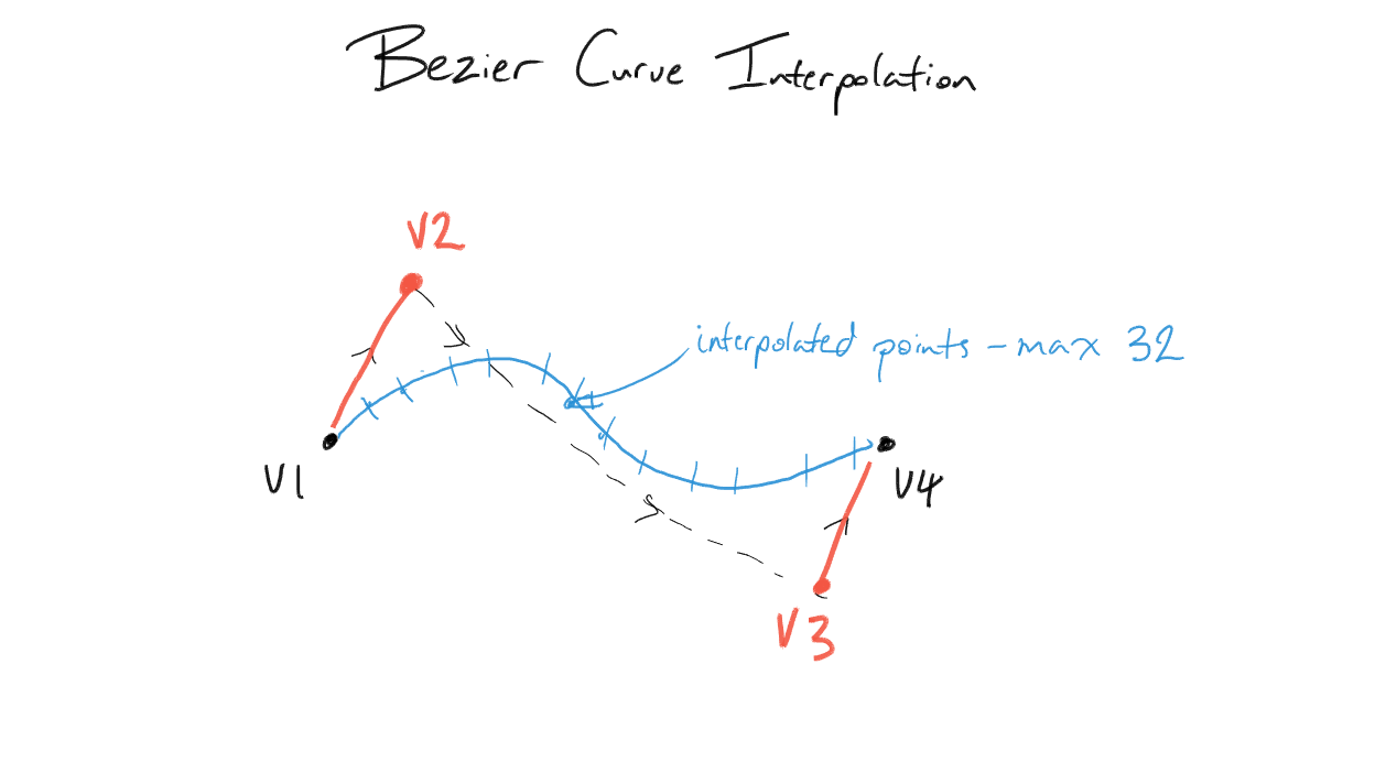
– We just use the maximum array size since it simplifies things, but also because the bezier routines in Blender (that are used for everything Bezier related, from 3D curves to F-Curves to B-Bones) can support at most 32 subdivisions between each pair of control points. This is why the Segments property is limited to 32 segments
2) The “rest” parameter is set to 0. In general, most of the time when working with BBones, you want to pass zero for this parameter, as you want to see the B-Bone with all the deforms (e.g. for visualising in the viewport, for constraints, or as part of calculating the final transforms).
However, it’s important to note that we can sometimes have rest == 1. As I discovered (when I finally figured out why the BlenRig rigs had been exploding), it is very important that we pay attention to this case, which gets called twice in Blender (once by the armature modifier when deforming geometry, and another when automatic weights are being calculated).
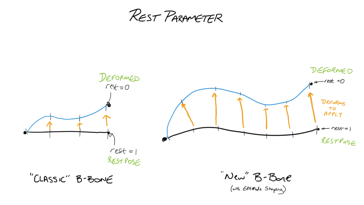
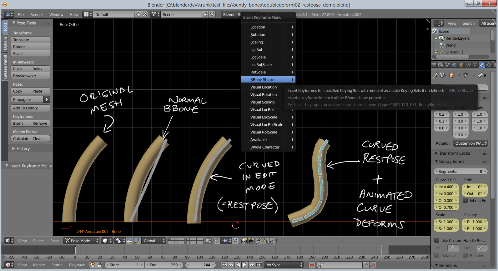
The “rest” parameter basically says whether we’re calculating the restpose shape of the BBone, or whether we’re computing the final deformed shape of the BBone.
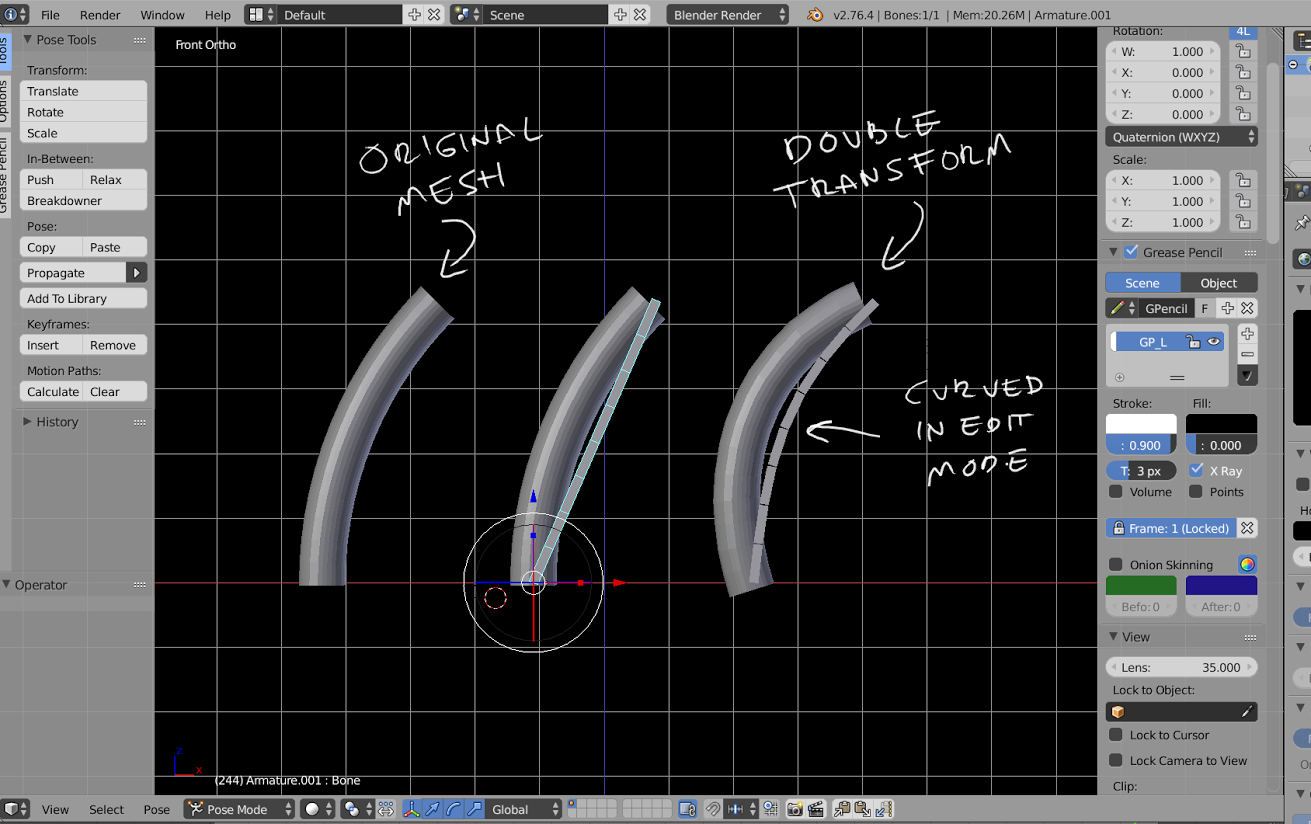 Bug – No restpose cancelling of BBone deforms == “Double Transform”
It is necessary to calculate the restpose of the bbone (and not simply use something dervied from the bone vector itself), as it allows us to do fancy stuff like “cancelling out” the contribution of the editmode shaping of the BBone from the final deform; if we don’t do this, you’d end up with points getting “double transformed” by the BBone (i.e. because we reshaped the BBone in editmode to match the geometry more, the BBone would deform the curved mesh further if we didn’t cancel out this restpose deform first). In other words, the final deform applied to the mesh is the difference between the restpose and deformed states of each segment.
3) All these transforms are in “bone space”. That is, all of these segments are calculated relative to the head and tail of the bone, and cannot just be used standalone. Instead, you need to multiply these by the bone’s “pose matrix” (i.e. pchan->pose_mat) to get these in pose space, if you want to be able to make another bone follow the shape of the B-Bone – that’s how the new “Follow B-Bone Shape” option for the Head/Tail target locations for Constraints works.
How B-Bones Work
So, how exactly do B-Bones work?
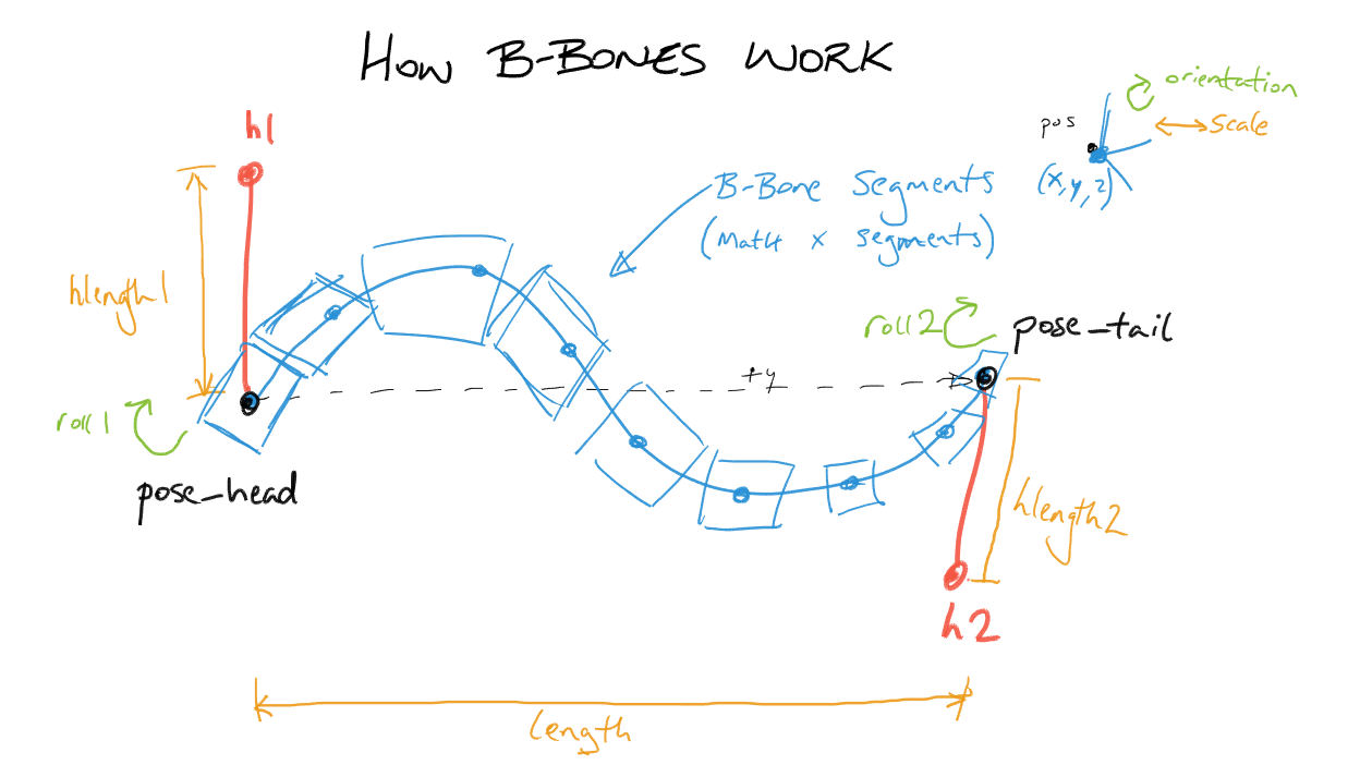
We treat the bone as a section of a Bezier curve – in much the same way we’d treat a section of a F-Curve between two keyframes.
- Each “B-Bone segment” of the bone represents a tesselated point of the Bezier curve.
- The control points at each end of the curve are the endpoints of the bone.
(pose_head = v1, pose_tail = v4) - We construct handles on either end of the bone to control its curvature
(h1 = v2, h2 = v3) - We also compute a “roll” value (or twisting around the main – y – axis of the bone), and do so per-segment, by interpolating between the start and end roll values
(roll1 = start roll, roll 2 = end roll) - For each segment, we can also introduce some scaling effects to adjust the thickness of each segment (see notes on extension points)
 The real magic to getting Bendy Bones here is in how we determine where those handles are relative to the control points, and how long they are.
- “Classic” B-Bones did this by using the endpoints of the next and previous (i.e. first child and parent) bones as the coordinates of the handle points (h1 and h2 respectively).
- “New” B-Bones apply offsets to these handle positions (Curve Offset X/Y) on the plane perpendicular to the bone’s primary (y) axis, on top of whatever the “base” h1/h2 positions were. More on this later…
- “New” B-Bones also have the option to use specific (potentially unrelated) bones for the next/prev handles. More on this later too…
- And, if all else fails, we just use some “default” handles, which are in line with the bone along the y-axis…
  h1 = (0, hlength1, 0)
  h2 = (0, -hlength2, 0)
* Knowing the position of the handle vertex, we convert that to an orientation by normalising, and scale by the handle length. So,
 h1_final = normalise(h1) * hlength1
 h2_final = normalise(h2) * hlength2
* The length of each handle (hlength1 and hlength2 respectively) is based on the “Ease In/Out” properties, the length of the bone, and a magic-number factor (“0.5f * sqrt(2) * kappa”, where kappa = the handle length – apparently this formula allows “for near-perfect circles”). i.e.,
 hlength1 = ease_in  * length * 0.390464f
 hlength2 = ease_out * length * 0.390464f
Code Structure
Knowing the general idea of how B-Bones work, how do we translate those insights into features? How is it implemented, and what does that mean about how we can extend it?
First, here is a little diagram of all the main parts of the code. Note that this is before the new B-Bones features were added:
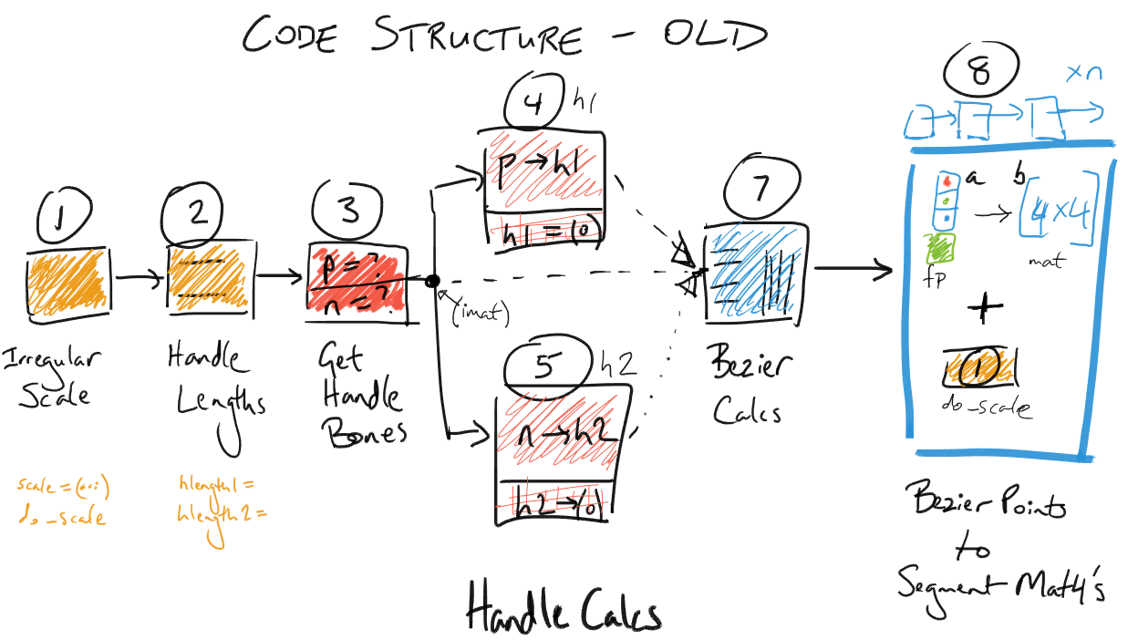
So, what do each of these parts do?
1) Irregular Scale – This tests if non-uniform scaling is being applied (i.e. one of the axes is fatter than the others). If so, some scaling corrections will need to be applied to the bone length (and again later – in step 8).
NOTE: Be careful about the checks here. I ran into a bug where the new B-Bones (just the offsets, no traditional bone-handles were involved) were flattening out when the bone was being scaled up by about 8.15 – 8.16. It turns out that due to floating point precision errors (it checks for 1 ^ -6 differences between values), it was occasionally tagging the bone as having non-uniform scaling when it passed through that range, causing the bone length to go from ~1 to > 8. As a result, the new B-Bone offsets were overpowered, causing the bone curve to flatten out!
2) Handle Lengths – This just calculates the length of each handle (hlength1, hlength2) from the bone length and the Ease In/Out settings
3) Get Handle Bones – This tries to get the next (child) and previous (parent) bones to act as handles for the B-Bone. If the parent is not connected to the bone, it isn’t used.
4) Compute Handle Verts for h1 – This computes the coordinates of h1 (the starting handle). The logic here works something like this:
if prev != null:
   # Use previous bone as handle 1
   h1 = convert_to_bbone's_local_space(prev.pose_head)
   h1 = normalise(h1) * hlength1

   if prev.segments == 1: # control bone, not bbone
       roll1 = interpolate_prev_roll(prev)
   else:
       roll1 = 0
else:
    # Use dummy, bone-aligned handle
    h1 = (0, hlength1, 0)
    roll1 = 0
5) Compute Handle Verts for h2 – Just like step 4, except this works on h2, and uses the tail of the next bone. It also tries to do a bit more “stuff”
if next != null:
    # Use next bone as handle 2
    h2 = convert_to_bbone's_local_space(next.pose_tail)
    if next.segments == 1: # control bone, not bbone
         h2.y = -length
    h2 = normalise(h2)
    roll2 = interpolate_next_roll(next)
    h2 *= hlength2  # only negate the handle now...
else:
    # Use dummy, bone-aligned handle
    h2 = (0, -hlength2, 0)
    roll2 = 0
7) Bezier Calculations – This is the step where the bone vertices (pose_head, pose_tail), handles (h1, h2), and roll values (roll1, roll2) get evaluated as a Bezier curve. It is done per-axis – treating each one as a Bezier curve itself, before the roll is also calculated in a similar manner. The result of this step is that we get an array of 4-item tuples (x,y,z + roll) – represented as a flat array – that has the coordinates we need for the next step…
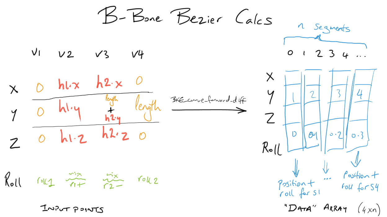
8) Compute Per-Segment Transforms – Here’s where we wrap things up, converting the point + roll tuples (8a) from the Bezier curve evaluation into the 4×4 transform matrices needed (8b) by everyone else. Then, if irregular scaling was detected (in step 1), scaling corrections need to be applied to this matrix… The resultant 4×4 transform matrices are stored in result_array.
Implementing New Features – Extension Points, and How the New B-Bones Work
Now, let’s see that diagram again, with all the new parts added (highlighted):
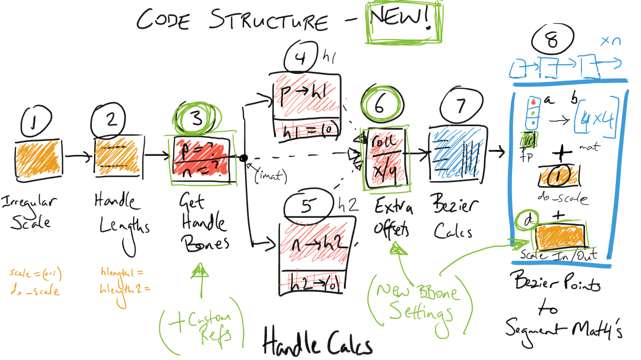
The following steps were added/modified for the following reasons:
- 6, 8d – (Added) – These steps are where the Bendy Bone magic happens! See next section for details about what and why.
- 3 – The “Use Custom BBone Reference” option is implemented here. It’s probably quite simple to see how this can be implemented: When the option is on, just use the specified bones instead of using trying looking at the bone’s neighbours.
- 4, 5 – The “Use Relative” options for Custom BBone references are implemented here. This is because instead of using the endpoints of the bones as absolute points in 3D space which we then map into the bone’s space to use as its handles, we instead take a look at where the reference bones are relative to their restpose – this delta transform is then applied as to the bone’s own endpoints to get the handle locations.
How the New Bendy Bone Options Work
As a reminder, here are the new controls that have been added for B-Bones, with annotations showing how they work:
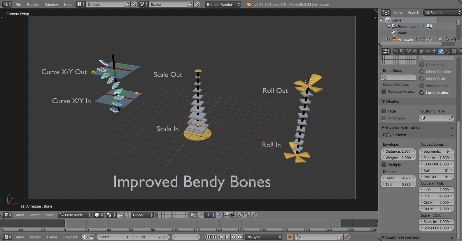
Here’s how those properties are mapped to the B-Bone evaluation method:
* Affect’s Bezier Curve Calculations => Applied in Step 6 as offsets to these values…
– Roll In/Out –> roll1, roll2
– Curve X/Y In –> h1
– Curve X/Y Out –> h2
So, the Roll values are basically rotational offsets applied on to of the rotation stuff that already has to happen.
The Curve X/Y values work by skewing the pushing the handles further out on the plane perpendicular to the main axis (y). As a result, the handle moves further from its original location, causing the curve to bend.
* Affect’s B-Bone Segments (but doesn’t impact the curve calcs) => Applied in 8d over the top of whatever else is already there…
– Scale In/Out –> Scale In and Scale Out are combined together to get a “combined scale factor” (for X and Z axes only, to affect the segment thickness but not its length). The influence of each factor is made to fade out over the length of the bone chain, going from each end to the other. Then, this scaling transform gets premultiplied with the existing transform matrix to get the final result.
The “Rest Pose” for Curved Bones
Sometimes, it’s useful to be able to have the B-Bone start off curved. For example, if you have a model with some curved facial features you wish to deform using B-Bones, if the B-Bones could only only be straight lines (as previously) the weighting wouldn’t be so great (as the B-Bone didn’t match the geometry). Instead, you’d end up having to add a whole lot more bones to compensate!
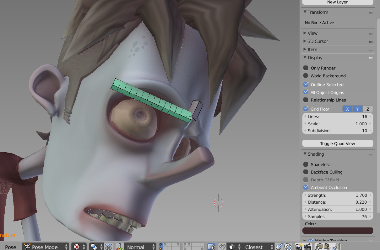
Motivation for Curved B-Bone Rest Poses – Character from Abel Tebar
By having the ability to define some initial curvature for B-Bones (i.e. for the restpose of the bones, in editmode), this problem could be solved! That’s what we’ve done here…. Implementing it was simply a matter of having two sets of the Bendy Bone properties – one for Bone/EditBone (i.e. the RestPose/Base Rig) and another for PoseBone (i.e. what animators work with) – and adding together their values to get the final transforms.
The only complication is that we need to account for the restpose shape when computing the necessary deforms, or else we get a “double transform” effect (see notes above regarding the “rest” parameter to b_bone_spline_setup())
Other Assorted Notes
* Constraints Head/Tail option follows curvature of B-Bones – There are times when it’s useful to allow constrained bones to follow the shape of B-Bones, without having to set up an additional complex system of additional bones to do the same thing.
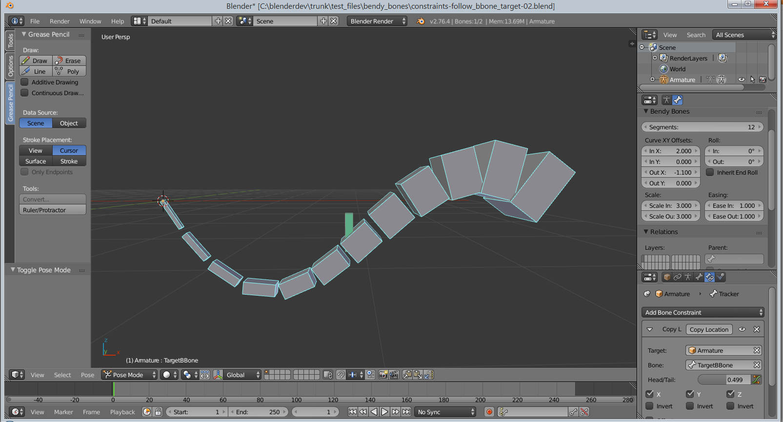
It turns out that implementing this is quite simple in fact! You just need to call b_bone_spline_setup(pchan, 0, bbone_segments); then you have the segments that you can perform some interpolation with to get the final transform. And so far, performance doesn’t really seem to be bad enough that we’d want to cache these off instead…
* Edit Mode preview of B-Bone curvature shape – Previously, there was no real B-Bone preview in EditMode. You could see that a B-Bone had a certain number of segments, but that was it. And really, it was sufficient, as in EditMode, the bones by definition are all in the rest poses, so there really should not be any bending going on with the “Classic” handles.
However, if we want to have curved restposes for B-Bones, we also need a way to see how they look. I ended up having to create a copy of b_bone_spline_setup() – ebone_spline_preview() in drawarmature.c – that is used for this purpose. It only calculates the Bendy Bone effects (since the others don’t make sense), and it does so using EditBones (as PoseBones and Bones don’t exist; it would have been messier to have tried to make a hacky adapter to get an EditBone looking enough like a PoseBone + Bone combo to get this working using the standard method)
* Deformation Quality – I’m really not much interested/skilled in deformation quality (or rendering or mocap for that matter) work. Instead, I mostly focus on issues of control schemes, interaction methods, tools, and animation system cores. As such, any questions regarding the quality of B-Bone deforms, or how those work are not covered here.
For details about those, go consult the armature modifier for further details about how it uses the B-Bone info gained from b_bone_spline_setup(). My guess is that it calculates delta matrices for each segment, and then interpolates between these to deform points that are affected by such bones. Smoother deforms may be possible if we added an extra smoothing step in there somewhere, instead of just using the result.


Hi Aligorith,
thanks for your great work, bendy bones are really awesome! I understand that you are too busy to make bendy bones exportable via FBX etc, so I wanted to propose a work-around which would really help game developers like myself.
If you could ‘expose’ (or make queryable) the transforms of bone segments in such a way that normal bones could be constrained to bone segments, it would be really easy for riggers to create a mapping rig (with normal bones) that contains all the information from bendy bones. If only bones from the mapping rig are marked as ‘deform’, there would be no information lost in the FBX export.
Now I understand that bone segments dont really have transforms, but I don’t think that matters. All that’s important is that the Copy X-constraints accept a bone segment as ‘Target’, right?
Do you think such a solution would be feasible?
Hi , thanks for the exiting new bbone , that opens up a whole new way of animating in blender , I have one feature request though , is it possible to sketch bbones using G pencil strokes, for fitting the rest pose for bbones to curved surfaces , This would save a lot of time adjusting the parameters to fit a particular surface say on a face . Also I guess you might be working on the sketch pose tools too this i the most exiting times for animators. Thanks a lot…
Hi ANANDAROOP,
Yes! This is one of the top 5 things I’d most like to get around to working on :)
Unforutnately, I’ve currently got a few too many projects with tight deadlines to finish, so it will be a few more months before I get around to it. But, all things going well, I hope to resume work on this in May/June this year :)
Hi there. Is there a way, either now or in the near future, to export Bendy Bones for use in a game engine or other application? It would be great to have a checkbox for “Real Bones” that either replaces or adds standard bones that mimic the B-Bones and we could bind our meshes to those and export those bones to fbx.
Hi Alec,
Currently there are no plans to add such support. But, it does sound like a good idea for a new addon (or as a feature built into the FBX exporter) ;)
“Currently there are no plans to add such support. But, it does sound like a good idea for a new addon (or as a feature built into the FBX exporter) ?”
Would this feature be implemented by the end of the year? If not could I send a money incentive to have it implemented?
Hi Ben, I agree that this feature would be super useful. I also think that it could be implemented in a simpler way, with a workaround (see my comment below). Let me know what you think.
ENG: thank you very much for this, this feature is great ….
Would it be possible to get to subdivide maintain bone curvature and scale relative to the original bone?
ES: muchas gracias por esto, es estupenda esta función….
¿sería posible conseguir que al subdividir el hueso mantengan la curvatura y escala relativa al hueso original?
Thanks so much for this BBones tutorial, Jason!!!
Now, for beginner Blender learner, if you really want to learn Blender, you should try to empty your cup first. And learn Blender fresh without any judgement.
Whatever previous tool you have: Maya, Blender, 3dsmax, Cinema4D, Softimate, you must see Blender as a new tool.
In 1-2 months time, you will get used to:
1) Blender RMB click
2) Blender 3D Cursor
3) Blender Layout
Then, discover all the good stuffs. Blender is really awesome.
You will be surprise by the $$$$ license you pay for big brother 3D software and what Blender offers as open source.
Rigging tutorials in Blender is very rare. The only good ones I found is DVD by Nathan Veghdal and also I was taught by Jeremy Davidson at some point at Puppeteer Lounger. Jeremy has one of the nicest facial setup using Bendy Bones and bone constraints.
Maya rigging is really nice. Blender is also great once understood.
— a tiny advice from Blender Sushi Guy (still learning Blender)
I always hoped that Blender was easier to use, especially when it comes to manipulating objects and the camera with the mouse. Still trying to move the camera with the mouse, the most popular have these system and Blender has not even for addon. I hope that in the future, Blender is recommended for beginners as well.
Right click the camera or left click the camera from the outliner to select it. You can then use “G” to move, “R” to rotate, “S” to scale, etc.
You can also use constraints (the icon looks like two chain links) in the properties panel to make the camera look at an object in your scene no matter where it is moved.
Choose camera, press “0”, press “shift+F”.
Fly around using FPS mouse & keyboard style controls, with E=up, Q=down.
Very impressive work.Its near the same like a curve but unfortunatly the the y-axes handle offset seams not controlable with the custom handle reference ( Handle lenght in the y local direction of the pose handle).
Its easy to add a driver for the In/Out Y slider but its static its seams not possible to add a driver for the driver f curve handle value.
But a curve handle seams to react like that I can change the handle offset by scaling and if i rotate the aligned handle to zero i get a straight curve. I tried the same setup with the bendy bone added a driver for easy in slider controlled by the refence handle rotation but as i said its not possible to add a driver for the driver handle value.
What i like most is the option to stretch to alonge the b bone shape i used before a curve with bones follow path with different offset…much more work.
hopfully reference handles get the option to change the y In/Out by Y scaling (bone lenght in pose mode).
Anyway Great Great improvment.
While bones are fresh in your mind, I have a question. Voodoo has a very cool method of automatic weighting where bone envelopes can be scaled non-uniformly on their axes, allowing for a much better approximation of form for characters. A heat-weight based solution is then used for weighting, but rather than performing a search from joint/bone centers, a raycast search is done from the bounds of the scaled envelopes to find proper weighting points. It results in a much cleaner and faster auto-weight than any other system I’ve used, especially when combined with the Delta Mush (corrective smooth in Blender). My question is, how difficult would adding non-uniform envelope scaling and the improved weighting be?
i second Matt’s suggestion
Hi Matt,
That’s an interesting suggestion, and is something that could be nice to explore.
I’m actually not that familiar with how the envelope stuff works exactly, since it is a separate code path to the B-Bones stuff, which is also separate to the heat weighting code. That said, I did just take a look into it quickly now.
1) First, I would look into making envelopes more useful in general, as a starting approximation. You’d want to modify distfactor_to_bone() in armature.c
-> It currently assumes that the endpoints/profile are spheres. Change those to ellipsoids (https://en.wikipedia.org/wiki/Ellipsoid) to get non-uniform stuff.
-> There may still be some complications with the final distance calculation (a “distance from center of sphere with falloff”, type of thing), which is calculated for an interpolated point somewhere along the length of the bone.
2) Then, you’d need to modify the heat weighting code to take into account what you’re talking about. But, I suspect that even just making envelopes have non-uniform thickness around their central axis will be enough to make them a lot more useful than they are now :)
This is amazing! I saw the last Blender Conference where Daniel Martinez Lara spoke this thread. I would like to suggest the method to bind the B-Bones with the mesh, a simply way to skin and paint weights. In Modo, for example, you bind and you skin with a simply click on viewport, in a vertex way of skinning. Its is possible? When it will available the BBones in Blender? All the Best. Happy Blender Day.
In order to prevent spam, comments are closed 7 days after the post is published. Feel free to continue the conversation on the forums.